Table of Contents
- Introduction
- Assemble the Parts
- Configure the Radio
- Wire up the Circuit
- Use it!
1) Introduction
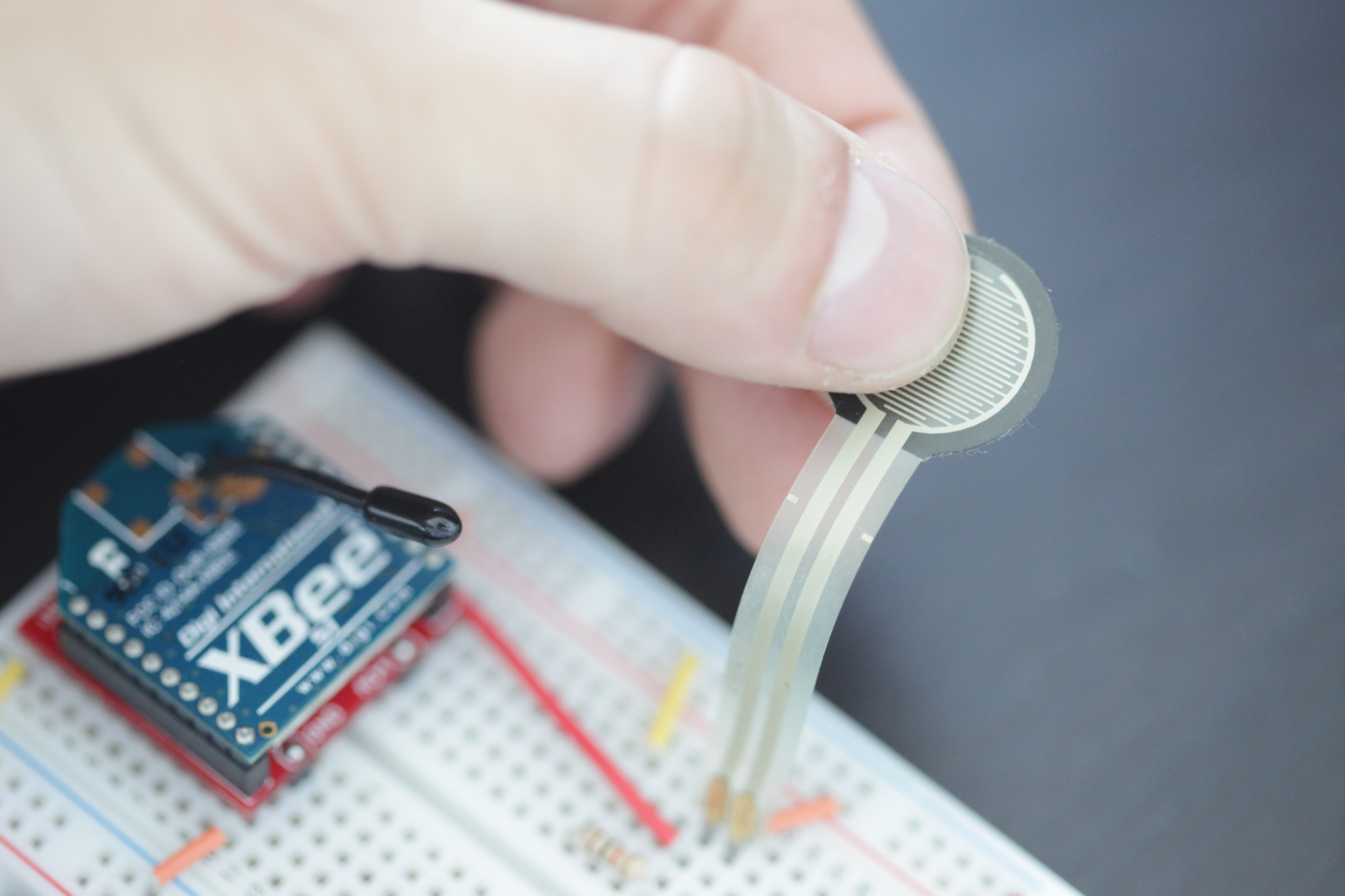
As opposed to a simple push button, force sensitive resistors (FSR's for short) can sense how hard a user is pressing down. The resistance across the two leads on an FSR varies based on how much pressure is on the pad. With no pressure, there's no continuity between the two leads. When you push softly, a connection is made between the two leads with some resistance. As you start pushing harder, the resistance drops.
By connecting the FSR to one of the two analog inputs on an XBee, we can create a wireless force sensor. This guide will walk you through how to configure and wire up an 802.15.4 XBee radio (Series 1) to read and transmit the levels from an FSR.
2) Assemble the Parts
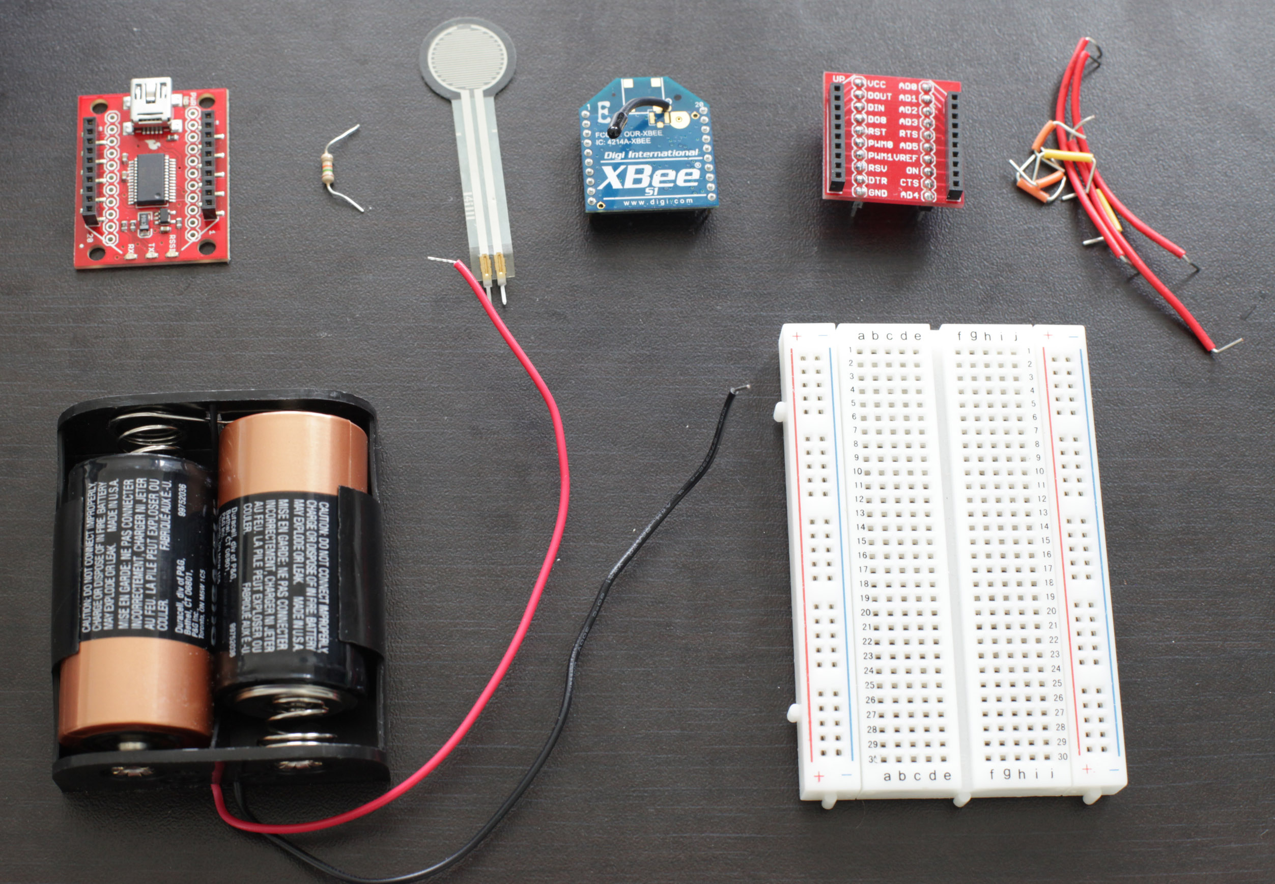
To hook up a force sensing resistor to an XBee, you'll need:
- XBee 802.15.4 Radio
- Force sensitive resistor - available from Adafruit, Sparkfun, and many others.
- Resistor - The resistance will depend on your FSR (it should be on the same order of magnitude as the resistance on your FSR). We're using a 1K resistor because our FSR has a resistance of around 1K when when push on it with medium force.
- Breadboard
- Jumper cables
- XBee Breakout Board - for your circuit.
- XBee Explorer USB - for programming your radio.
- A DC power source, 2.8 - 3.3V - We'll be using two C batteries in a battery holder from Radio Shack.
4) Wire up the Circuit
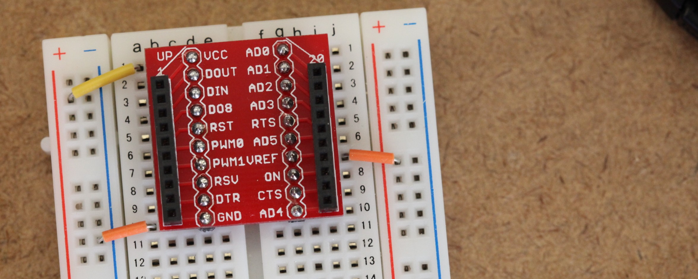
- Place the XBee adapter into the breadboard and wire up the power buses to each other.
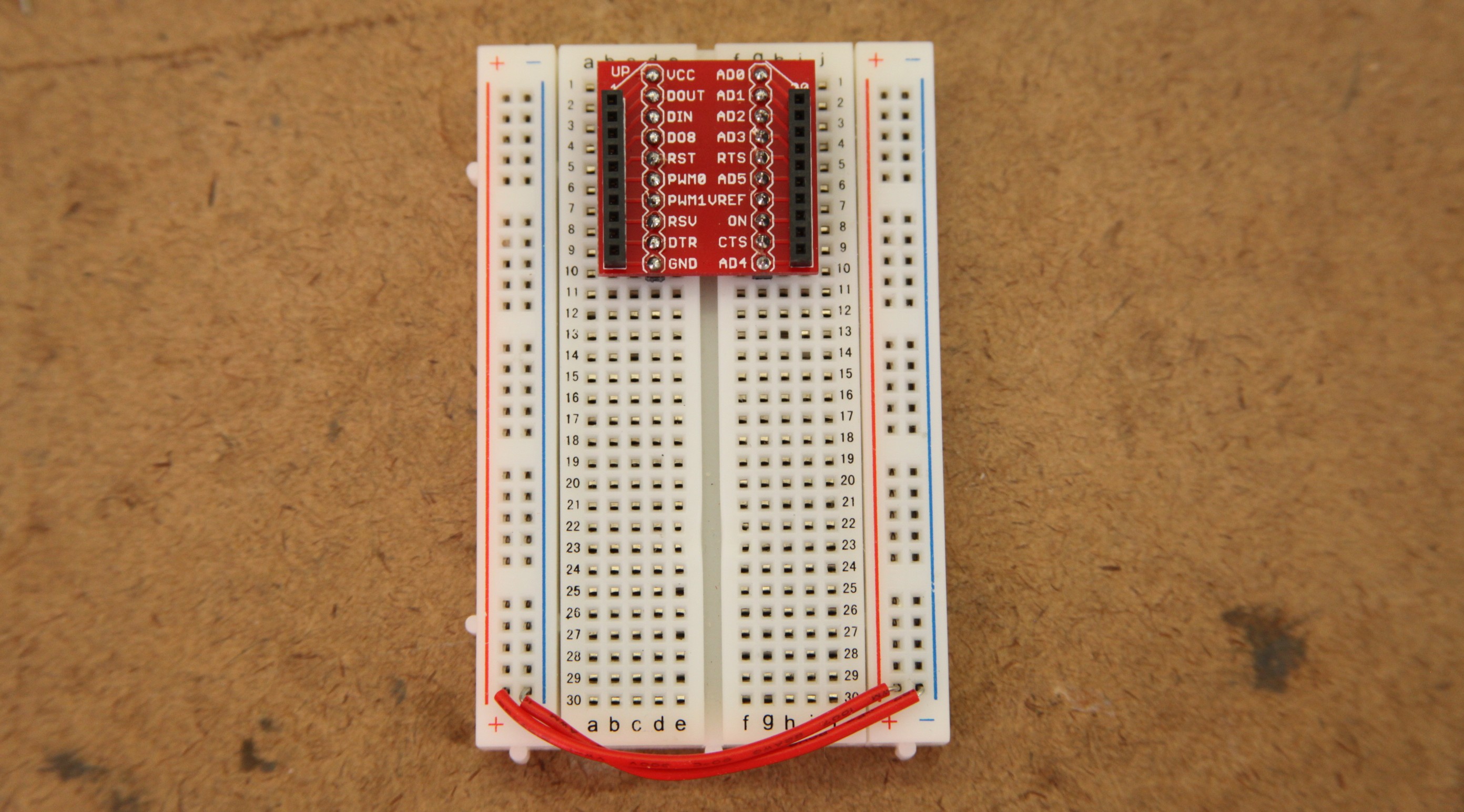
- Connect the VCC terminal of the XBee adapter to the positive rail and the ground terminal to the negative rail.
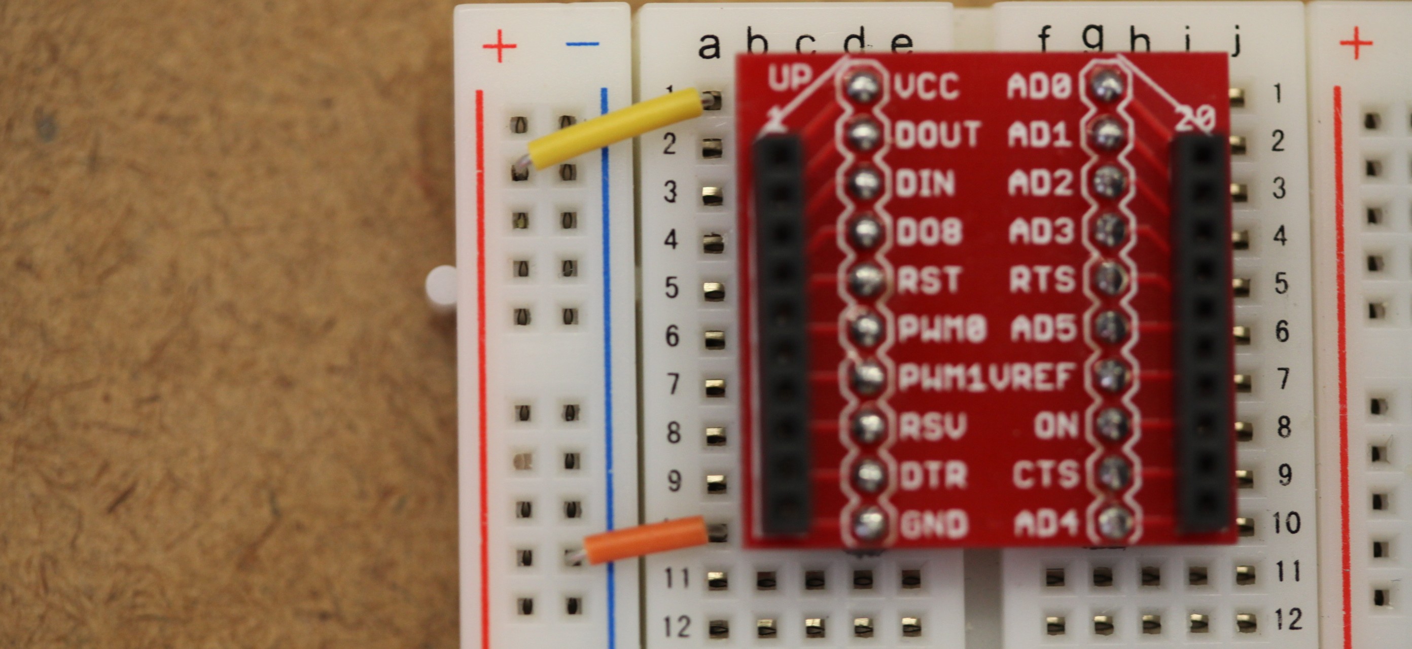
- Connect the VREF terminal of the XBee adapter to the positive rail. This will give the XBee a reference for what voltage an analog sensor is working with.
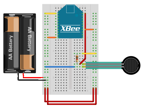
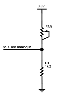
- Connect one lead of the FSR to the positive voltage rail, and the other lead to pin 20 of the XBee. It doesn't matter which sides of the FSR you choose, it's not polarized. Place the resistor between ground and the FSR lead that connects to the XBee. This creates a simple voltage divider circuit.
- This is what the voltage divider looks like as a schematic diagram.
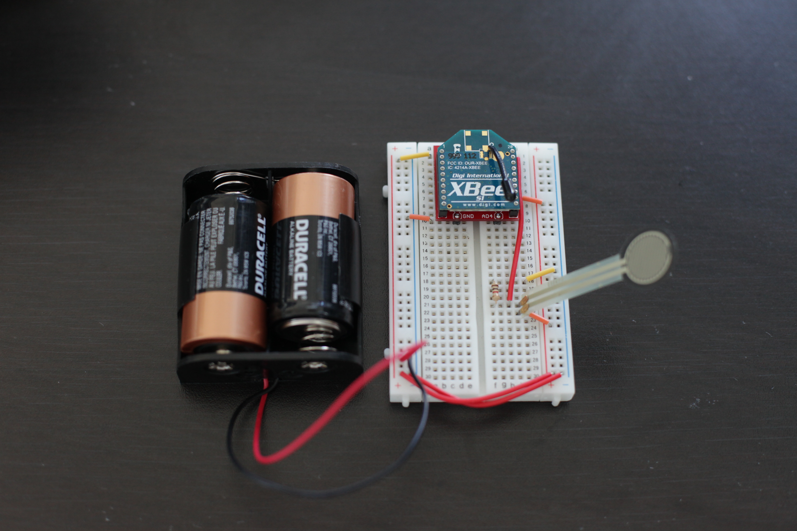
- Here's how your circuit might look as laid out on a breadboard.
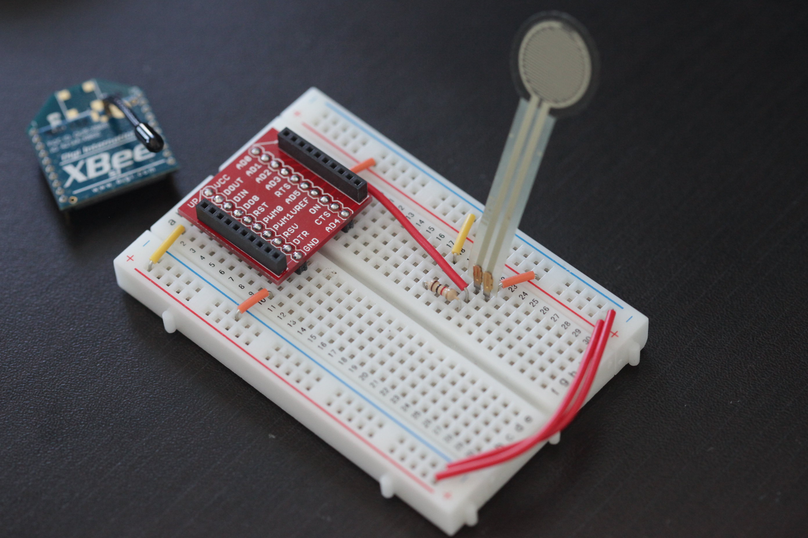
- Insert the XBee into the breakout board and connect the battery pack.
5) Use it!
Now that you know how to connect a force sensing resistor to the analog input of an XBee radio, take a look at our output tutorials for how you can output force information. Just be sure that the the transmitter's address is set as the receiver's I/O input address setting (ATIA). The video above shows a wireless FSR connected to a wireless LED.