Introduction:
This is Part 3 of the DMVPN (Dynamic Multipoint VPN) Knowledge Base series, which details the configuration of DMVPN on Digi routers.
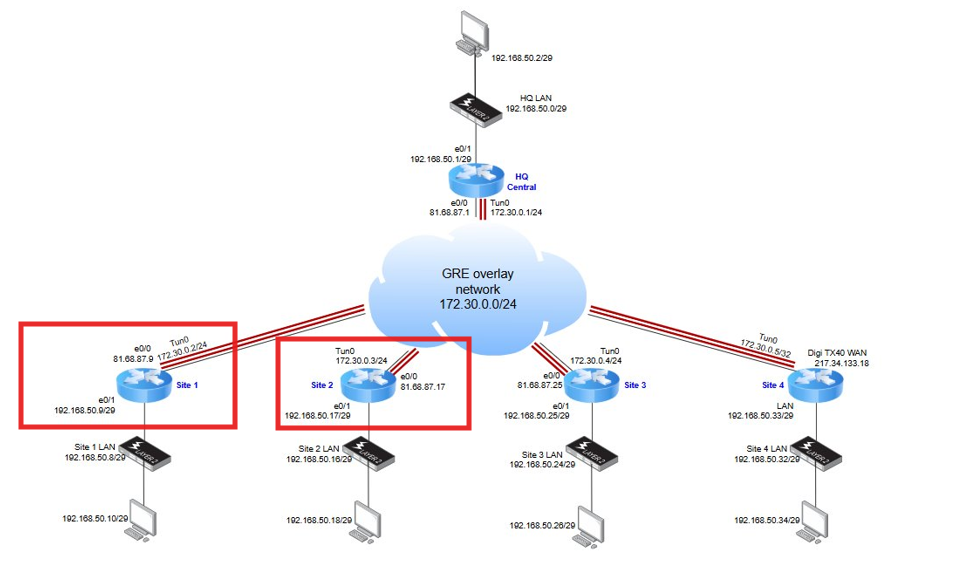
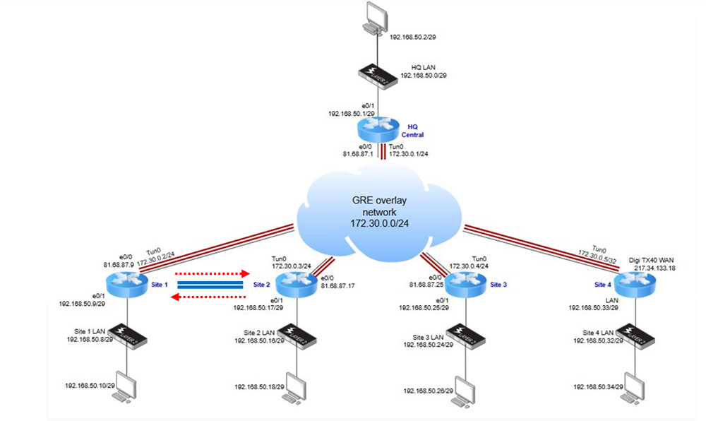
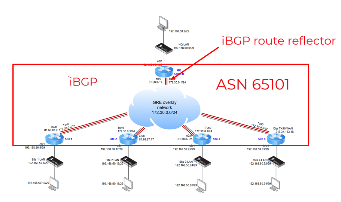
In this article, we focus on configuring the Remote Sites 1 and 2 (Cisco Spokes), based on the following network deployment scenario:
1. Network Configuration
After establishing an SSH connection to the Cisco router, the following configurations were applied on both routers:
- LAN and WAN interfaces configured according to the addressing scheme outlined above
- NAT Overload enabled for internet access via the WAN interface
- Default route set to forward all outbound traffic to the upstream gateway
For details on command used, you can reference to DAL DMVPN Part.2 KB
2. IPsec and IKEv2 Configuration
For this deployment, IKEv2 is used as the key exchange protocol. The Phase 1 and Phase 2 parameters are configured as follows:
- Phase 1 (IKEv2 Proposal):
Protocol: IKEv2
Encryption: AES 128
Integrity: SHA1
Diffie-Hellman Group: 5
Authentication Method: Pre-Shared Key
- Phase 2 (IPsec Proposal):
Encryption: AES 128
Integrity: SHA1
Perfect Forward Secrecy (PFS): None
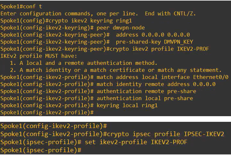
On each Spoke, enter configuration mode and use the following commands to define the IKEv2 keyring and the IKEv2 profile.
The profile will include the pre-shared key and a reference to the keyring.
Then, set the IPsec profile linking it tot he IKEv2 phase 1 profile
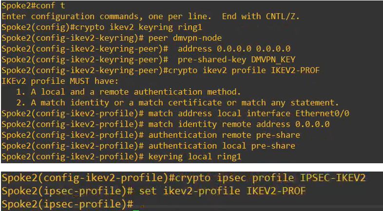
Below is the expected output you will see on the router while configuring this section on both sites:
Site 1
SIte 2
The resulting configurations will be the same for both Site 1 and Site2:
crypto ikev2 keyring ring1
peer dmvpn-node
address 0.0.0.0 0.0.0.0
pre-shared-key DMVPN_KE

crypto ikev2 profile IKEV2-PROF
match address local interface Ethernet0/0
match identity remote address 0.0.0.0
authentication remote pre-share
authentication local pre-share
keyring local ring1
crypto ipsec profile IPSEC-IKEV2
set ikev2-profile IKEV2-PROF
2. Tunnel Interface Configuration (mGRE)
Same as fort he HUB, also on the Spokes we configure a mGRE tunnel inyerface setting the following:
- IP address using a /24 subnet mask. This subnet size is necessary because the tunnel will operate in multipoint GRE (mGRE) mode.
- Tunnel source, which can be either a physical interface or a specific IP address on the router.
- Tunnel mode to gre multipoint to support multiple GRE peers over a single logical interface, which is essential for DMVPN.
- Apply IPsec Protection Profile to secure the GRE traffic
- Adjust MTU Settings to 1400: this is important to prevent fragmentation issues caused by the additional overhead introduced by GRE and IPsec headers.
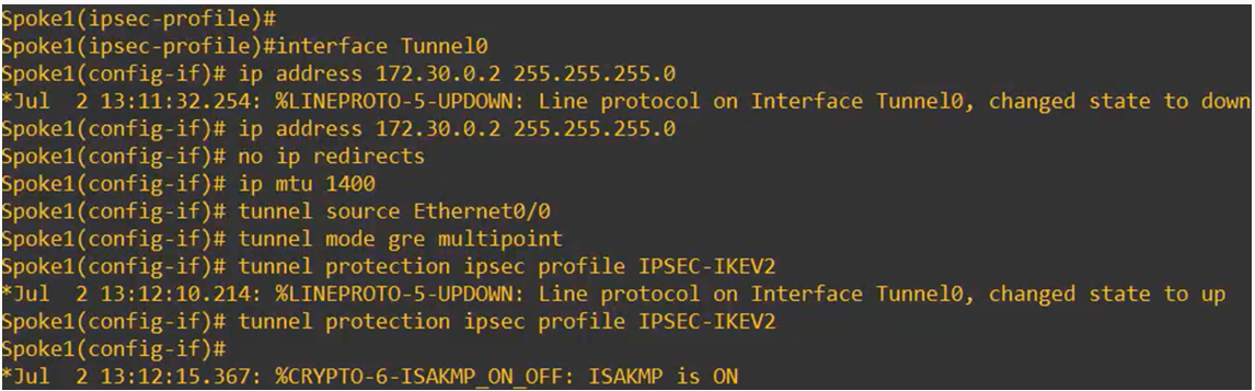
Below is the expected output you will see on the router while configuring this section for the two Sites.
Site 1
Site 2
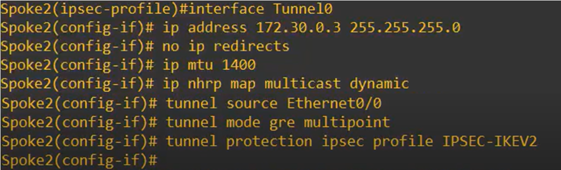
The resulting configuration will be for the two Sites:
Site 1
interface Tunnel0
ip address 172.30.0.2 255.255.255.0
no ip redirects
tunnel source Ethernet0/0
tunnel mode gre multipoint
tunnel protection ipsec profile IPSEC-IKEV2
ip mtu 1400
Site 2
interface Tunnel0
ip address 172.30.0.3 255.255.255.0
no ip redirects
tunnel source Ethernet0/0
tunnel mode gre multipoint
tunnel protection ipsec profile IPSEC-IKEV2
ip mtu 1400
4. NHRP Configuration
For the remote site, the NHRP configuration under the tunnel interface will include the following elements:
- Enable dynamic multicast mapping
- NHRP Map Command: This maps the overlay address to the public IP address of the HQ router. Based on the network scheme referenced above, these are:
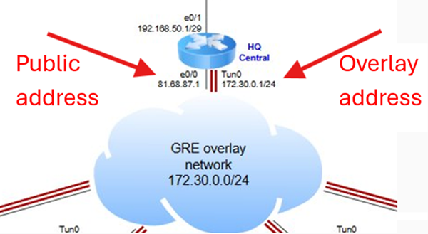
- NHRP Map Multicast Command: Uses the same public IP address of the HQ router to enable multicast traffic forwarding.
- NHRP Network ID: Must match the network ID configured on the HQ router to ensure consistency across the DMVPN network.
- NHRP Next Hop Address (nhs): Specifies the tunnel interface IP address of the HQ router as the next hop for NHRP resolution.
- NHRP Shortcut Command:Enables direct spoke-to-spoke communication, allowing site-to-site routing without the need to traverse the hub:
Below is the expected output you will see on the routers while configuring this section:
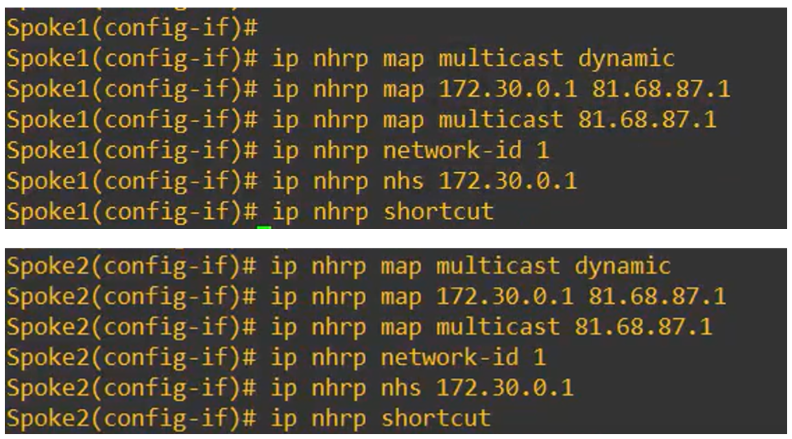
The resulting configuration will be the same for both routers:
Site 1 & Site 2
interface Tunnel0
 ip nhrp map multicast dynamic
 ip nhrp map 172.30.0.1 81.68.87.1
 ip nhrp map multicast 81.68.87.1
 ip nhrp network-id 1
 ip nhrp nhs 172.30.0.1
 ip nhrp shortcut
5. BGP Configuration
All routers in this network will participate in iBGP using the same Autonomous System Number (ASN 65101):
On the each spoke router, the following configurations must be applied:
- Enable BGP with ASN 65101(same as set on the HQ router)
- and setting the mGRE address oft he HQ as neighbour with the same ASN
- Advertise the LAN network using the address family command) and activate this BGP configuration
- Enable log-neighbor-changes to monitor BGP session status changes.
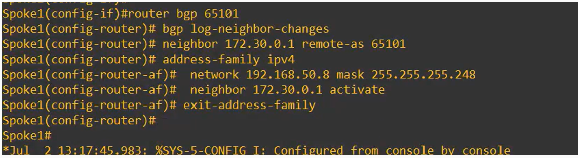
Below is the expected output you will see on the routers while configuring this section:
Site 1
Site 2
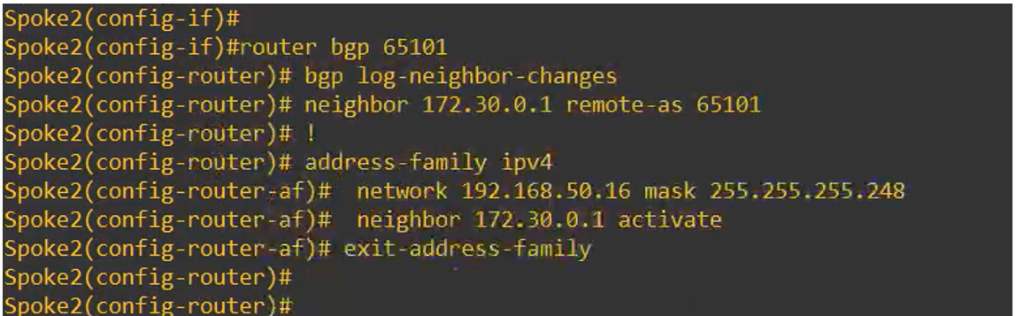
The resulting configuration will be:
Site 1
router bgp 65101
bgp log-neighbor-changes
neighbor 172.30.0.1 remote-as 65101

address-family ipv4
 network 192.168.50.8 mask 255.255.255.248
 neighbor 172.30.0.1 activate
exit-address-family
Site 2
router bgp 65101
bgp log-neighbor-changes
neighbor 172.30.0.1 remote-as 65101

address-family ipv4
 network 192.168.50.16 mask 255.255.255.248
 neighbor 172.30.0.1 activate
exit-address-family
6. Complete DMVPN Cisco Spokes configuration:
To finalize the setup, make sure to save the configuration so that all changes persist after a reboot.
Below is the complete DMVPN configuration applied to the Central Cisco Spoke routers:
Site 1
crypto ikev2 keyring ring1
 peer dmvpn-node
  address 0.0.0.0 0.0.0.0
  pre-shared-key DMVPN_KEY
!
!
crypto ikev2 profile IKEV2-PROF
 match address local interface Ethernet0/0
 match identity remote address 0.0.0.0
 authentication remote pre-share
 authentication local pre-share
 keyring local ring1
!
crypto ipsec profile IPSEC-IKEV2
 set ikev2-profile IKEV2-PROF
!
interface Tunnel0
 ip address 172.30.0.2 255.255.255.0
 no ip redirects
 ip mtu 1400
 ip nhrp map multicast dynamic
 ip nhrp map 172.30.0.1 81.68.87.1
 ip nhrp map multicast 81.68.87.1
 ip nhrp network-id 1
 ip nhrp nhs 172.30.0.1
 ip nhrp shortcut
 tunnel source Ethernet0/0
 tunnel mode gre multipoint
 tunnel protection ipsec profile IPSEC-IKEV2
!
interface Ethernet0/0
 ip address 81.68.87.9 255.255.255.248
 ip nat outside
 ip virtual-reassembly in
!
interface Ethernet0/1
 ip address 192.168.50.9 255.255.255.248
 ip nat inside
 ip virtual-reassembly in
!
interface Ethernet0/2
 no ip address
 shutdown
!
interface Ethernet0/3
 no ip address
 shutdown
!
router bgp 65101
 bgp log-neighbor-changes
 neighbor 172.30.0.1 remote-as 65101
!
 address-family ipv4
  network 192.168.50.8 mask 255.255.255.248
  neighbor 172.30.0.1 activate
 exit-address-family
Site 2
crypto ikev2 keyring ring1
 peer dmvpn-node
  address 0.0.0.0 0.0.0.0
  pre-shared-key DMVPN_KEY
!
!
crypto ikev2 profile IKEV2-PROF
 match address local interface Ethernet0/0
 match identity remote address 0.0.0.0
 authentication remote pre-share
 authentication local pre-share
 keyring local ring1
!
crypto ipsec profile IPSEC-IKEV2
 set ikev2-profile IKEV2-PROF
!
interface Tunnel0
 ip address 172.30.0.3 255.255.255.0
 no ip redirects
 ip mtu 1400
 ip nhrp map multicast dynamic
 ip nhrp map 172.30.0.1 81.68.87.1
 ip nhrp map multicast 81.68.87.1
 ip nhrp network-id 1
 ip nhrp nhs 172.30.0.1
 ip nhrp shortcut
 tunnel source Ethernet0/0
 tunnel mode gre multipoint
 tunnel protection ipsec profile IPSEC-IKEV2
!
interface Ethernet0/0
 ip address 81.68.87.17 255.255.255.248
 ip nat outside
 ip virtual-reassembly in
!
interface Ethernet0/1
 ip address 192.168.50.17 255.255.255.248
 ip nat inside
 ip virtual-reassembly in
!
interface Ethernet0/2
 no ip address
 shutdown
!
interface Ethernet0/3
 no ip address
 shutdown
!
router bgp 65101
 bgp log-neighbor-changes
 neighbor 172.30.0.1 remote-as 65101
!
 address-family ipv4
  network 192.168.50.17 mask 255.255.255.248
  neighbor 172.30.0.1 activate
 exit-address-family
Further Information
Related Video: [link]
Next KB of the series: [link to part4]
Introduction and KB/Video Index: [link to KB - 0 that contains all video/kb list and links]
Last updated:
Mar 04, 2026