* Using API mode it is possible to send AT commands from a transmitting radio to a receiving radio. This allows for module parameter registers on remote devices to be queried or set.
One useful application of this feature is to toggle an IO on a remote radio from a high to a low state. In this manner the radios can be used as a wireless relay to control a wide variety of remote devices.
Overview
In this tutorial we will be using X-CTU to create and send 2 distinct API frames. One frame will toggle the remote radios IO high, and the other will toggle the remote radios IO low. You could easily program a micro-controller or other piece of hardware to issue these commands.
Setup
To perform this tutorial you will require the following materials:
2 - Digi XBee ZB RF modules.
2 - Interface boards (USB or RS232) *the use of Digi XBIB interface boards will allow the use of on board LEDs to observe output.
1 - PC with X-CTU software installed
Serial or USB cables to connect interface boards to the PC.
Procedure
Program 1 radio as a Coordinator (with API enabled) and other radio as a Router node.
Both radios are programmed with the default settings. And in my example, have the following 64 bit addresses:
Coordinator:
SH=0013A200
SL=418D2B4C
Router:
SH=0013A200
SL=418D0506
Connect the Coordinator to the PC and launch X-CTU. Power up the Router on the other XBIB interface board.
Create two remote AT command (type 0x17) frames, paying close attention to the structure of this frame as outlined in the API frames section of the module's product manual.
Here are the frames configured for the address of my radios. Your packets will contain the address of your router radio and the checksum will need to be recalculated.
Note: I have chosen to toggle DIO4 as it is connected to LED 3 on the XBIB board and allows easy viewing of the toggle process without the use of a voltmeter or scope.
Command to set DIO4 high:
7E 00 10 17 01 00 13 A2 00 41 8D 05 06 FF FE 02 44 34 05 DD
Command to set DIO4 Low:
7E 00 10 17 01 00 13 A2 00 41 8D 05 06 FF FE 02 44 34 04 DE
You can make use of "Frames Interpreter" tool in XCTU for easy understanding of these API frames.
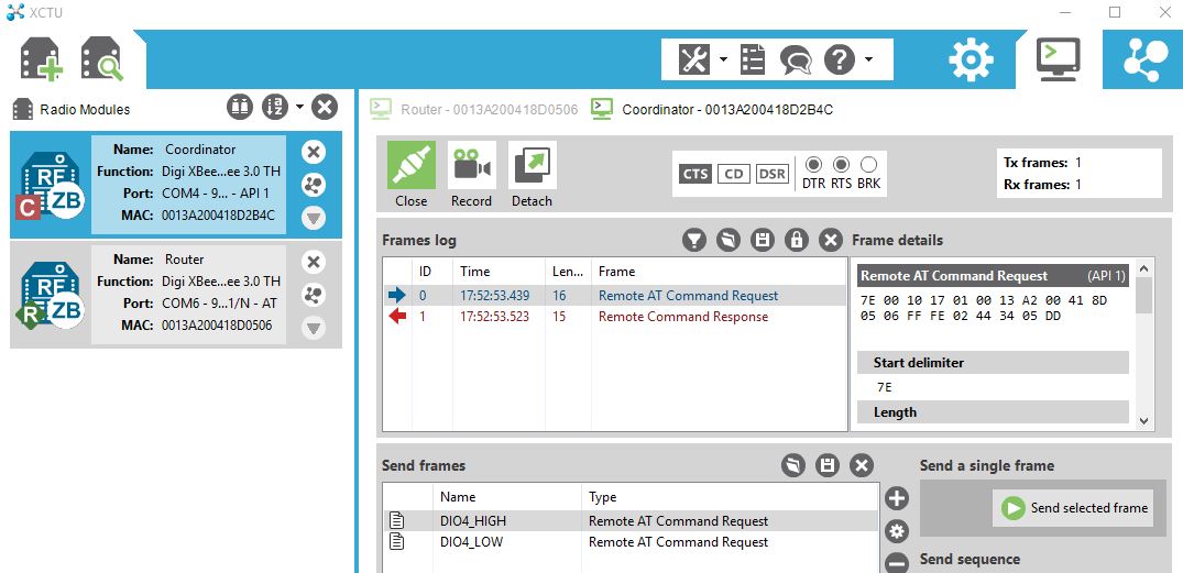
Open the Console tab in X-CTU and enter the API command as shown below

Click the "Send selected frame" button. You should see your packet displayed in the X-CTU's main window in blue followed by a response packet in red. If you do not receive a response, check your packet for accuracy. Definitions of the remote AT command (0x17) and the remote command response (0x97) can be found in product manual.
On the Receiving radio you should see the LED 3 go off when the set high command is sent on go on when the set low command is set. You may also verify the state by connecting a multi-meter to Pin 11 of the module to check its voltage state as it is toggled from High to low. The pin should read about 3.3v when high and about 0 volts when low.
Note: This article is written using Digi XBee3 ZB radios but the concepts are applicable to most of the XBee Radio lineup that offer API mode.