A unique feature of the
Digi XBee 802.15.4 modules is the ability to perform digital I/O line passing. Essentially, this feature enables the user to toggle the state of any DIO pin on a transmitting radio and have that same pin on one or more receiving radios toggle their state to match the change. This functionality is an easy way to wirelessly control relays or any other switched equipment.
Note: DIO line passing can only be done with XBee 802.15.4 modules.
Components used in this tutorial:
- Two XBee 802.15.4 radios
- Two XBee Grove Development Boards
- Two Micro USB cables
To get started with this example, configure the pin of the XBee where the button is connected as digital input, and configure the pin of the XBee where the LED is connected as digital output. You will also need to configure the first XBee to send a notification to the other XBee when the button changes state.
Lets get started.
Follow along with this video as we write the parameters described above to both of our XBee radios.
Bonus Tip: Boost the reliability of the XBee connection by setting a sample rate on the transmitting XBee (Parameter: IR). If there happens to be interference while the data is being transmitted, it might not be received by XBee B. Setting a sample rate will ensure the change of state is communicated by the following sample rate packets.
Have the radios all set and ready to go? When the button connected to the the transmitting XBee is pressed, the LED of the receiver will light. Cue the drum roll....
If the application requires multiple receiver nodes, the change of state can be sent as a broadcast. To do this, modify the destination low address to "FFFF" on the transmitting radio. Note that this concept of DIO line passing is not specific to only pin 4, it can be applied to any DIO pin on the XBee 802.15.4 module.

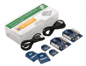
For this tutorial we used the new
XBee Grove Development Board found in the Wireless Connectivity Kit.
Visit Digi-Key to learn more about this new kit.
Next Steps